

 shqiptare
 euskara
 Zulu
Zulu
 Latinus
 Cymraeg
 தமிழ்
தமிழ்
 Slovak
 Slovak
 Afrikaans
How to wire a split phase inverter
Nov 14,2025
How to Wire a Split Phase Inverter: Complete Manufacturer’s Installation Guide
Wiring a split phase inverter is one of the most essential steps when building a 120/240V power system for homes, workshops, RVs, tiny houses, or off-grid cabins. As a manufacturer specializing in OEM/ODM split phase inverters for global markets, we see one challenge repeatedly: most installation problems are caused by incorrect wiring, not the inverter itself.
This extended guide explains how to wire a split phase inverter safely, correctly, and efficiently, following the same technical principles we provide to distributors, installers, and engineering teams.
What Is a Split Phase Inverter? (Manufacturer Explanation)
A split phase inverter is designed to deliver dual-voltage AC output—120V and 240V—from a single inverter unit.
It is commonly used in regions such as:
• United States
• Canada
• Mexico
• Caribbean
• Philippines (some areas)
• Off-grid communities using North American voltage standards
Inside the inverter, an internal transformer or H-bridge circuitry creates:
• L1 (Hot Leg 1, 120V)
• L2 (Hot Leg 2, 120V)
• These two legs are 180° out of phase, producing 240V when combined
So you get:
• 120V between L1 and Neutral
• 120V between L2 and Neutral
• 240V between L1 and L2

This design supports both low-voltage and high-voltage home appliances.
Why Proper Wiring Matters
Many issues like:
• voltage imbalance
• frequent overload warnings
• neutral-ground faults
• inverter shutdowns
• humming noise
• failed GFCI devices
…are caused by wiring, not hardware.
With correct installation, you get:
• higher efficiency
• stable AC output
• safer operation
• longer lifespan
• minimum complaints from clients

How to Wire a Split phase Inverter step by step :
Step 1: Identify the Terminals Correctly
Typical AC output of a split phase inverter includes:
| Terminal | Meaning | Voltage |
| L1 | Hot Leg 1 | 120V to Neutral |
| L2 | Hot Leg 2 | 120V to Neutral |
| N | Neutral | Balanced reference point |
| PE / Ground | Earth ground | Safety protection |
Incorrect identification is the #1 cause of installation failures.
Step 2: Connect the Battery Bank (DC Side)
Voltage Requirements
• 24V systems → 24V battery bank
• 48V systems → most common for 5–12kW inverters
• High-voltage battery like 170VDC-600VDC→ depends on inverter model
Manufacturer DC Wiring Tips
• Use short, thick cables to reduce resistance
• Install a proper DC breaker or fuse
• Ensure correct communication (CAN/RS485) with LiFePO₄ batteries
• Avoid mixing BMS brands unless supported(Pls check the battery communication protocal before buying the inverter and batteries to make sure the compatibility)

Correct DC wiring ensures stable waveform output and reduces switching noise.
Step 3: Connect AC Output (L1, L2, N)
For 120V Loads
Connect:
• L1 → Load → Neutral
or
• L2 → Load → Neutral
For 240V Loads
Connect:
• L1 → Load → L2
Do NOT use neutral for 240V.

Load Balancing Is Critical
A well-balanced system means:
• Less heat
• Less current stress
• Higher efficiency
Try to distribute loads evenly across L1 and L2.
Step 4: Connect Earth Ground (PE)
Proper grounding ensures:
• electrical safety
• lightning protection
• correct operation of RCD/GFCI
• stable neutral reference
Where to Bond Neutral to Ground?
In most countries following NEC:
• Neutral-to-ground bond must be in the main panel,
• NOT inside the inverter (unless it is listed as a bonded system)
Always follow regional electrical codes.
Step 5: Connect PV, Generator, or Grid Input
PV Wiring
• PV+ → PV+
• PV– → PV–
Ensure string voltage is within MPPT window.
Generator/Grid Wiring
If the inverter has AC input:
• Connect L1 / L2 / Neutral / PE exactly according to the label
• Do not reverse AC-IN with AC-OUT
Incorrect wiring may damage the transfer relay.

Step 6: Startup Procedure
1. Turn on the battery breaker
2. Turn on the inverter AC breaker
3. Turn on PV or generator input
4. Power up inverter and test with a multimeter:
• L1–N ≈ 120V
• L2–N ≈ 120V
• L1–L2 ≈ 240V
If readings are off—shut down and check wiring.
Common Wiring Mistakes (From Real Install Cases)
❌ Using Neutral for 240V appliances
→ Causes immediate damage.
❌ Putting all loads on L1
→ Causes high current, inverter overheating.
❌ Skipping grounding
→ Creates floating voltages, noise, or shock risk.
❌ Mixing AC-IN and AC-OUT
→ Damages the inverter transfer switch.
❌ Wrong gauge cables
→ Leads to voltage drop or fire hazard.
Recommended Tools for Proper Wiring
• True RMS multimeter
• Torque wrench for terminals
• DC breaker (sized per battery specs)
• SPD (surge protector) on both AC & DC sides
• Proper lugs and crimping tools
Advanced Tips from OEM Engineers
✔ Use a load distribution box designed for split phase
Avoid DIY panel wiring—it causes unbalanced loads.
✔ Limit 240V loads during backup mode
Some inverters prioritize 120V loads to extend battery runtime.
✔ Update inverter firmware
Many performance issues are solved in newer firmware versions.
✔ Keep inverter cables below 3 meters
Long cables = noise + drop + instability.
FAQ for inverters:
1. What is the difference between split phase and single phase?
Split phase provides 120V + 240V, while single phase offers only one voltage (typically 110V or 230V). Split phase is better for homes with mixed appliances.
2. Can I wire a split phase inverter without a neutral?
No. Neutral is required for 120V loads.
Only 240V appliances don’t need neutral.
3. Do I need to balance loads on L1 and L2?
Yes. Balanced loads improve efficiency, reduce heat, and prevent overload trips.
4. Can a split phase inverter run 240V appliances?
Yes. Connect the appliance between L1 and L2.
5. Is grounding necessary for split phase systems?
Absolutely. Proper grounding ensures safety and stable AC output.
6. Can I connect a generator to a split phase inverter?
Yes—if the inverter supports AC-in bypass/charging.
Always match L1/L2 correctly.
7. Does a split phase inverter work off-grid?
Yes. Split phase inverters are widely used in off-grid homes and cabins.
8. What battery is best for split phase inverters?
LiFePO₄ with BMS communication is recommended for stability and lifespan.
9. Why do I get unbalanced voltage on L1 and L2?
Likely caused by:
• unbalanced loads
• loose terminals
• incorrect neutral-ground bonding
• wiring errors
10. Can I install a split phase inverter myself?
DIY is possible but not recommended.
Manufacturer guidelines + local codes = safe installation.
Conclusion
A split phase inverter provides both 120V and 240V power, making it ideal for North American homes and off-grid systems. With correct wiring, grounding, load balancing, and safety precautions, your system will run efficiently and reliably for many years.
As a professional split phase inverter manufacturer, we support OEM, ODM, project customization, and engineering assistance worldwide.
If you need:
• wiring diagrams
• datasheets
• OEM branding
• distributor pricing
• factory videos
We can provide everything you need.
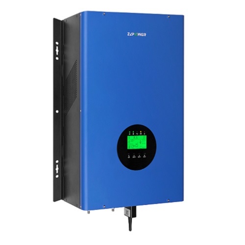
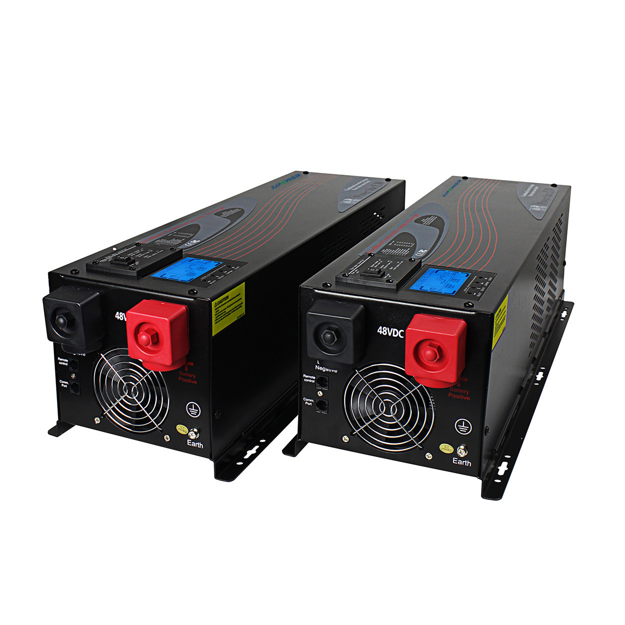
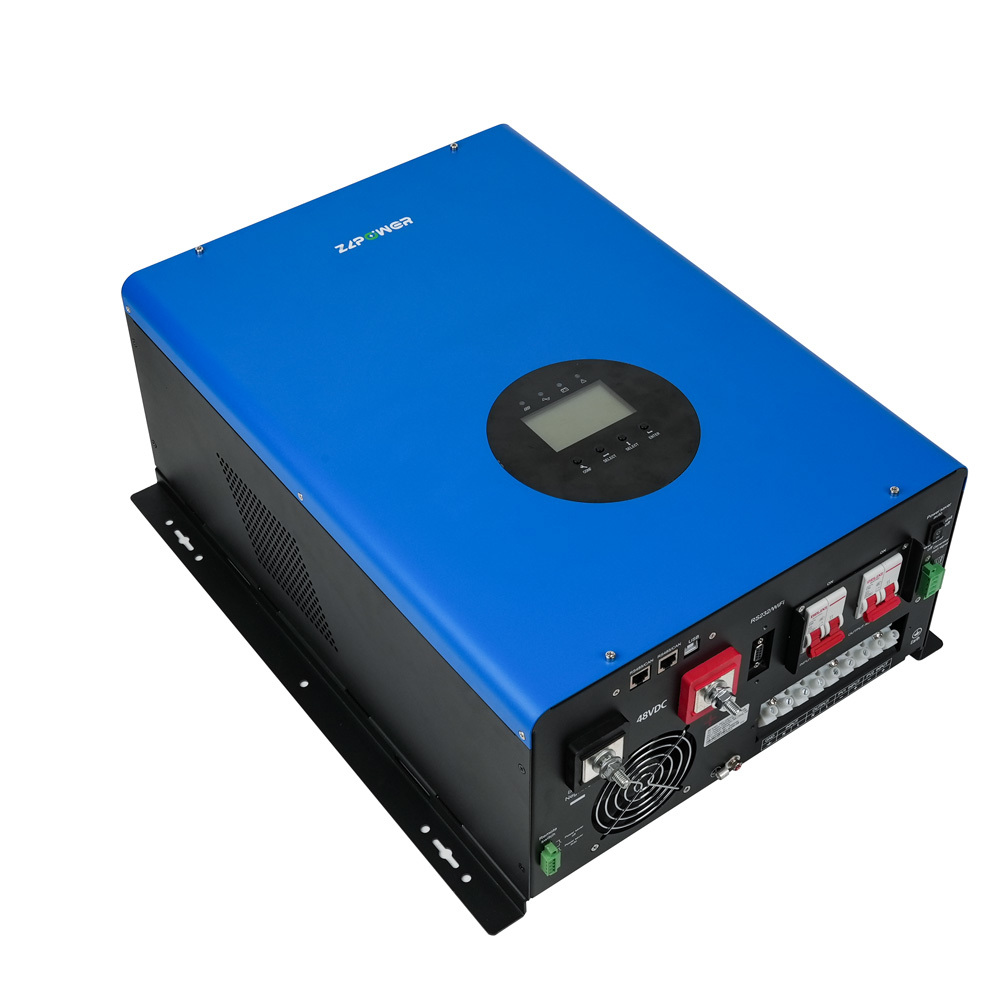
Not only split phase inverters,ZLPOWER Inverter manufacture side has More Optionals ,welcome to contact for OEM ODM price enquiry:



Related products

More News
How to Protect UPS from Rain?Weatherproof IP65 Battery Backup
w do you protect a UPS from rain, what makes an outdoor UPS rainproof, what are its key features, and what benefits can industries bank on? Let's address these questions in this blog.
Lithium Battery UPS:Why LiFePO4 Battery Is Revolutionizing Rugged Outdoor UPS Performance in 2026
As a leading R&D manufacturer of industrial power solutions, we are excited to announce our next-generation IP65 Rugged Outdoor UPS series integrated with high-density LiFePO4 technology. Engineered to withstand continuous temperatures from $-20^\circ\text{C}$ to $+65^\circ\text{C}$, our new pure sine wave online double-conversion systems deliver zero transfer time and 3,000+ deep cycles. Designed for harsh environments, this lineup offers global system integrators an unbeatable combination of rugged durability and factory-direct engineering support.
APC SYBTU2-PLP Battery Replacement 100% Compatible Symmetra PX Solution Save up to 50% by High-Performance SYBTU2-PLP Battery Pack Replacement for APC Symmetra PX
Looking to replace your APC SYBTU2-PLP battery modules without paying OEM markup?" Get 100% drop-in compatible replacements direct from our factory. Save up to 50% on Symmetra PX maintenance with certified 12V 9Ah packs, backed by free live installation support. 👉 Get a Factory Direct Quote Today
The Ultimate Buyer’s Guide to Rugged UPS: Thermal management, metallurgy, and battery chemistry
Technical & Manufacturing Overview Driven by engineering innovation, our factory stands at the forefront of industrial UPS research and manufacturing. We specialize in solving complex power protection challenges by engineering ruggedized, high-ingress protection (IP65/IP67) outdoor UPS systems equipped with smart thermal management and advanced battery chemistries (LiFePO4/VRLA). With in-house testing labs and a veteran R&D team, we offer comprehensive customization (OEM/ODM) to meet stringent international standards (CE, UL, IEC). From harsh desert microgrids to coastal industrial sites, we deliver factory-direct, pure sine wave power solutions that guarantee zero transfer time for critical automated loads.
Ultimate Guide to IP65 Outdoor UPS: Design Secrets & Customization Checklist
Custom IP65 Outdoor UPS Factory Rugged Outdoor UPS Manufacturer IP65 UPS for Extreme Weather Solicitud Oferta SAI Exterior Tailor-Made Industrial UPS OEM/ODM Outdoor Power Systems Heavy-duty IP65 Outdoor UPS built for your exact climate. Get a direct factory quote today. Dust-tight, waterproof & thermal-insulated UPS systems. Engineered for telecom & solar grids. Diseñado para entornos severos. Solicite su oferta de SAI industrial con protección IP65.
How to Choose The Right Modular UPS for Your AI Data center in 2026?
At ZLPOWER , we understand that in the era of AI and hyper-scale computing, power stability is the bedrock of digital transformation. With 18 years of specialized expertise, ZLPOWER has evolved into a global leader in the R&D and manufacturing of Modular UPS Systems. Operating from our state-of-the-art integrated factory and R&D center, we don’t just build hardware; we engineer comprehensive, one-stop power ecosystems tailored to the most demanding data center environments. ### Core Competencies & Innovation * 18 Years of R&D Mastery: Our journey spans nearly two decades of power electronics evolution. From the early days of telecommunications to the current 2026 AI-driven data center boom, our engineering team stays at the forefront of power conversion technology. * Modular "Pay-as-you-Grow" Architecture: Our flagship modular UPS series (including the 93M and 95M ranges) features true hot-swappable design and N+X redundancy. This allows operators to scale capacity seamlessly from 50kW to over 600kW without a second of downtime. * Deep Factory Customization: Unlike standard off-the-shelf providers, ZLPOWER operates its own dedicated R&D center. We provide bespoke modifications—from specialized PCB coating for harsh environments to integrated lithium-ion battery synchronization—ensuring our UPS fits your specific facility requirements perfectly. * Extreme Efficiency for Green Data Centers: Engineered for the 2026 sustainability standards, our systems achieve up to 96.5% efficiency in online double-conversion mode and feature intelligent "Smart Sleep" modes to minimize PUE and operational costs. ### Why Partner with ZLPOWER? * Direct Manufacturer Advantage: Skip the middleman. Partnering with our factory means direct technical support, faster lead times, and highly competitive pricing. * Proven Track Record: With thousands of successful deployments in IDCs, financial institutions, and medical networks worldwide, our reliability is field-tested and industry-proven. * One-Stop Service Loop: From initial load calculation and site survey to professional commissioning and 24/7 global after-sales support, we handle the complexity so you can focus on your core business.
Subscribe
Check the latest news of our company anytime and anywhere.
Contact ZLPOWER
1-2 Floor, Building E, Liyukeng Industrial Zone, Beihuan Road, Shangwu Community,Shiyan Street, Bao'an District, Shenzhen,Guangdong, China